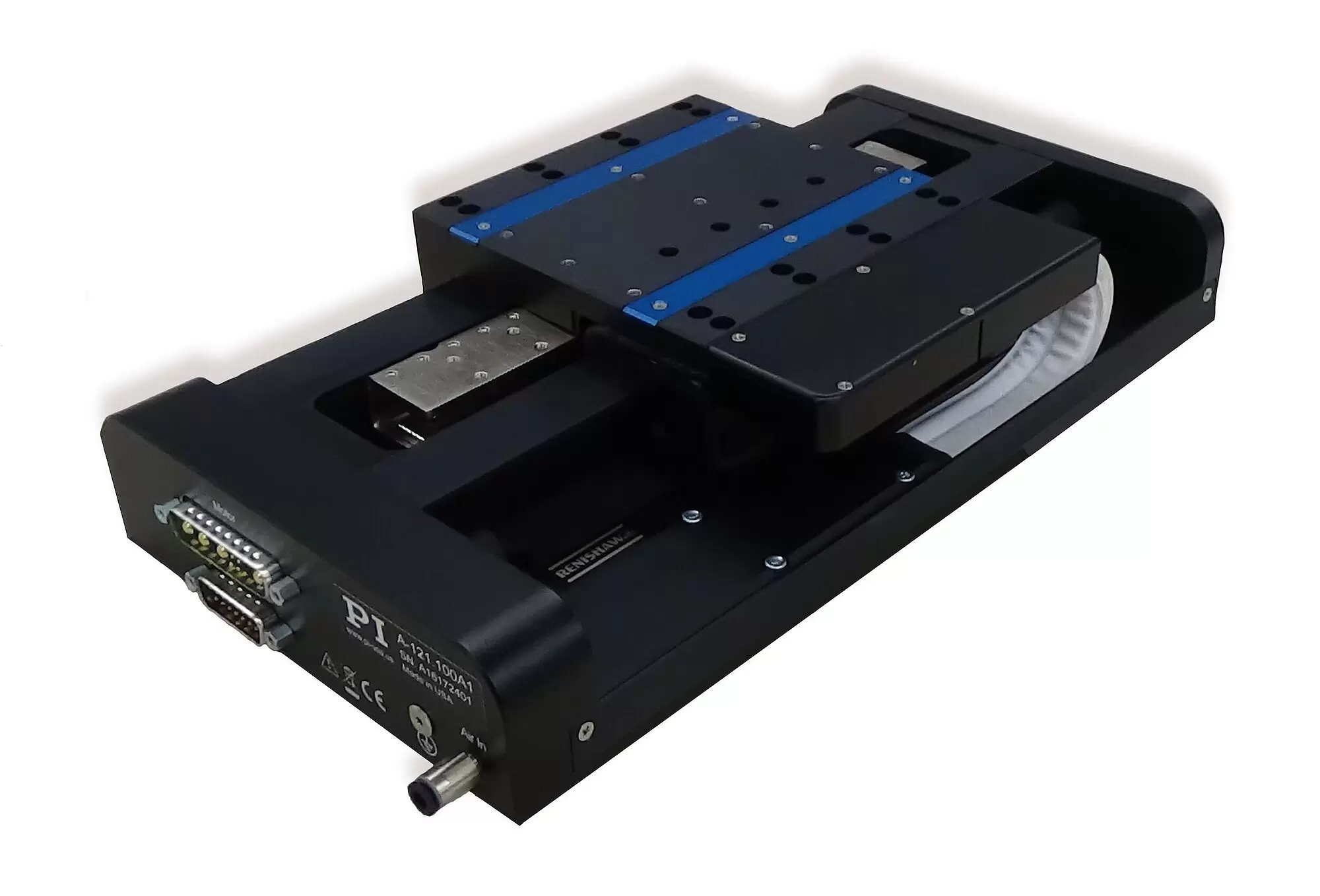
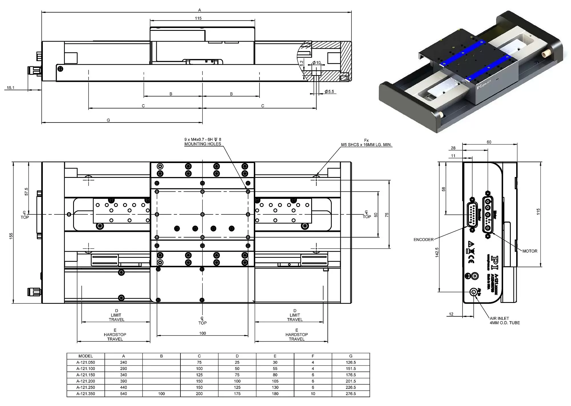
The stages in the PIglide are equipped with a servo drive linear motor with preloaded air bearings and integrated linear encoder. The combination of these noncontact components results in a frictionless motion platform that offers the highest performance, quality, and lifetime.
A high-force linear motor can drive the stage to top speed within a few milliseconds. The preloaded air bearing construction supports mounting in any orientation.
PIglide positioning systems are ideally suited for many high-precision applications such as metrology, photonics, and precision scanning in semiconductor or flat panel display manufacturing.
Thanks to the friction-free motion, no particles are formed, which makes PIglide stages ideal for cleanroom applications.
Motion | A-121.050 | A-121.100 | A-121.150 | A-121.200 | A-121.250 | A-121.350 | Unit | Tolerance |
|---|---|---|---|---|---|---|---|---|
Active axes | X | X | X | X | X | X | ||
Travel range | 50 | 100 | 150 | 200 | 250 | 350 | mm | |
Pitch / yaw (1) | 20 | 20 | 20 | 20 | 25 | 35 | µrad | Max. |
Straightness / flatness (1) | 0.5 | 0.5 | 1 | 1.5 | 2 | 2.5 | µm | Max. |
Straightness / flatness per 25 mm travel range (1) | 0.1 | 0.1 | 0.1 | 0.1 | 0.1 | 0.1 | µm | Max. |
Velocity, unloaded (2) | 0.5 | 1 | 1 | 1 | 1 | 1 | m/s | Max. |
Acceleration, unloaded (2) | 20 | 20 | 20 | 20 | 20 | 20 | m/s² | Max. |
Mechanical properties | A-121.050 | A-121.100 | A-121.150 | A-121.200 | A-121.250 | A-121.350 | Unit | Tolerance |
|---|---|---|---|---|---|---|---|---|
Load capacity in z (6) | 100 | 100 | 100 | 100 | 100 | 100 | N | Max. |
Load capacity in y (6) | 40 | 40 | 40 | 40 | 40 | 40 | N | Max. |
Permissible torque in θx (6) | 5 | 5 | 5 | 5 | 5 | 5 | Nm | Max. |
Permissible torque in θy (6) | 8.3 | 8.3 | 8.3 | 8.3 | 8.3 | 8.3 | Nm | Max. |
Moved mass | 1.2 | 1.2 | 1.2 | 1.2 | 1.2 | 1.2 | kg | Typ. |
Overall mass | 3.5 | 4.2 | 4.5 | 5.2 | 5.7 | 6.8 | kg | Typ. |
Guide type | Air bearing | Air bearing | Air bearing | Air bearing | Air bearing | Air bearing |
Drive properties | A-121 | Unit | Tolerance |
|---|---|---|---|
Drive type | Ironless 3-phase linear motor | ||
Intermediate circuit voltage, RMS | 48, nominal 80, max. | V DC | |
Peak current, RMS | 3.5 | A | Max. |
Nominal current, RMS | 1.2 | A | Max. |
Peak force | 33.2 | N | Max. |
Nominal force | 11.1 | N | Max. |
Force constant, RMS | 9.4 | N/A | Typ. |
Resistance phase-phase | 6.3 | Ω | Typ. |
Inductance phase-phase | 1.0 | mH | Typ. |
Back EMF phase-phase | 7.7 | V·s/m | Typ. |
Cabling | External, moving cable |
Positioning | A-121.xxxA | A-121.xxxB |
|---|---|---|
Integrated sensor | Incremental linear encoder | Absolute linear encoder |
Sensor signal | Sin/cos, 1 V peak-peak, 20 µm signal period | BiSS-C |
Sensor resolution | 4.88 nm (3) | 1 nm |
Bidirectional repeatability | ±0.25 µm | ±0.25 µm |
Positioning accuracy, uncalibrated (4) | A-121.050: ± 1.5 µm A-121.100: ± 1.5 µm A-121.150: ± 1.5 µm A-121.200: ± 2.0 µm A-121.250: ± 2.0 µm A-121.350: ± 3.0 µm | A-121.050: ± 1.5 µm A-121.100: ± 1.5 µm A-121.150: ± 1.5 µm A-121.200: ± 1.5 µm A-121.250: ± 1.5 µm A-121.350: ± 1.5 µm |
Positioning accuracy, calibrated (4) | A-121.050: ± 0.5 µm A-121.100: ± 0.5 µm A-121.150: ± 0.5 µm A-121.200: ± 0.5 µm A-121.250: ± 0.5 µm A-121.350: ± 0.5 µm | A-121.050: ± 0.5 µm A-121.100: ± 0.5 µm A-121.150: ± 0.5 µm A-121.200: ± 0.5 µm A-121.250: ± 0.5 µm A-121.350: ± 0.5 µm |
Miscellaneous | A-121 |
|---|---|
Operating pressure (5) | 65 to 75 psi (450 to 520 kPa) |
Air consumption | < 1.0 SCFM (28 SLPM) |
Air quality | Clean (filtered to 1.0 μm or better) - ISO 8573‑1 Class 1 Oil free - ISO 8573‑1 Class 1 Dry (-15 °C dew point) - ISO 8573‑1 Class 3 |
Materials | Hardcoat aluminum, stainless steel mounting hardware |
(1) Dependent on the flatness of the surface, on which the stage is mounted.
(2) Can be limited by the payload, controller or drive.
(3) Assumes 4096x interpolation. Contact PI for the use of other factors.
(4) Improved accuracy can be obtained with controller-based error compensation. The stage must be ordered with a controller from PI to reach these values. Accuracy values assume short duration and do not consider the long-term effects of thermal drift on the stage.
(5) To protect the stage against damage, it is recommended to connect an air pressure sensor to the Motion-Stop input of the controller.
(6) Assumes an air bearing operating pressure of 70 psi (480 kPa).