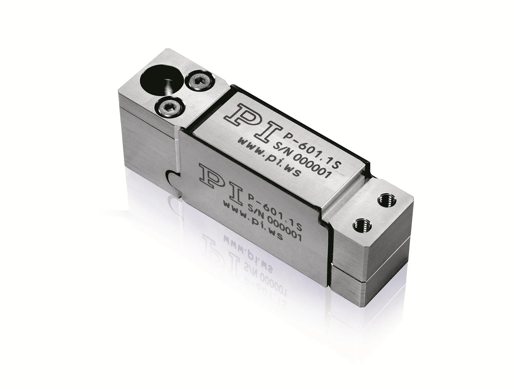
The patented PICMA® piezo actuators are all-ceramic insulated. This protects them against humidity and failure resulting from an increase in leakage current. PICMA® actuators offer an up to ten times longer lifetime than conventional polymer-insulated actuators. 100 billion cycles without a single failure are proven.
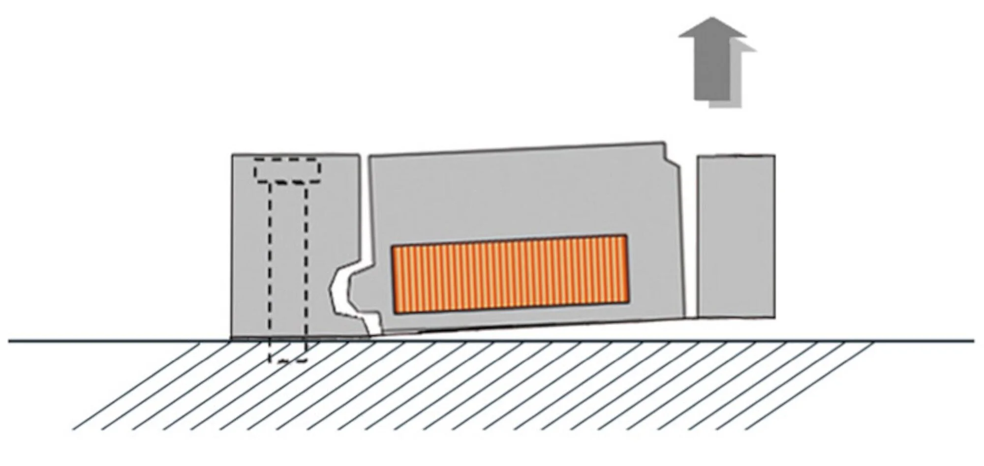
Flexure guides are free of maintenance, friction, and wear, and do not require lubrication. Their stiffness allows high load capacity and they are insensitive to shock and vibration. They work in a wide temperature range.
| Motion | P-601.10 | P-601.10L | P-601.1S | P-601.1SL | P-601.30 | P-601.30L | P-601.3S | P-601.3SL | P-601.40 | P-601.40L | P-601.4S | P-601.4SL | Tolerance |
|---|---|---|---|---|---|---|---|---|---|---|---|---|---|
| Active axes | Z | Z | Z | Z | Z | Z | Z | Z | Z | Z | Z | Z | |
| Travel range in Z, open loop, at -20 to 120 V | 100 µm | 100 µm | 100 µm | 100 µm | 250 µm | 250 µm | 250 µm | 250 µm | 400 µm | 400 µm | 400 µm | 400 µm | +20 / -0 % |
| Travel range in Z | 100 µm | 100 µm | 250 µm | 250 µm | 400 µm | 400 µm | |||||||
| Linearity error in Z | 0.1 % | 0.1 % | 0.3 % | 0.3 % | 0.3 % | 0.3 % | typ. | ||||||
| Positioning | P-601.10 | P-601.10L | P-601.1S | P-601.1SL | P-601.30 | P-601.30L | P-601.3S | P-601.3SL | P-601.40 | P-601.40L | P-601.4S | P-601.4SL | Tolerance |
| Resolution in Z, open loop | 0.2 nm | 0.2 nm | 0.2 nm | 0.2 nm | 0.3 nm | 0.3 nm | 0.3 nm | 0.3 nm | 0.4 nm | 0.4 nm | 0.4 nm | 0.4 nm | typ. |
| Integrated sensor | SGS, indirect position measuring | SGS, indirect position measuring | SGS, indirect position measuring | SGS, indirect position measuring | SGS, indirect position measuring | SGS, indirect position measuring | |||||||
| System resolution in Z | 2 nm | 2 nm | 6 nm | 6 nm | 12 nm | 12 nm | |||||||
| Repeatability in Z | 8 nm | 8 nm | 10 nm | 10 nm | 30 nm | 30 nm | typ. | ||||||
| Drive Properties | P-601.10 | P-601.10L | P-601.1S | P-601.1SL | P-601.30 | P-601.30L | P-601.3S | P-601.3SL | P-601.40 | P-601.40L | P-601.4S | P-601.4SL | Tolerance |
| Drive type | PICMA® | PICMA® | PICMA® | PICMA® | PICMA® | PICMA® | PICMA® | PICMA® | PICMA® | PICMA® | PICMA® | PICMA® | |
| Electrical capacitance in Z | 1.5 µF | 1.5 µF | 1.5 µF | 1.5 µF | 3.1 µF | 3.1 µF | 3.1 µF | 3.1 µF | 4.6 µF | 4.6 µF | 4.6 µF | 4.6 µF | ±20 % |
| Mechanical Properties | P-601.10 | P-601.10L | P-601.1S | P-601.1SL | P-601.30 | P-601.30L | P-601.3S | P-601.3SL | P-601.40 | P-601.40L | P-601.4S | P-601.4SL | Tolerance |
| Guide | Flexure guide with lever amplification | Flexure guide with lever amplification | Flexure guide with lever amplification | Flexure guide with lever amplification | Flexure guide with lever amplification | Flexure guide with lever amplification | Flexure guide with lever amplification | Flexure guide with lever amplification | Flexure guide with lever amplification | Flexure guide with lever amplification | Flexure guide with lever amplification | Flexure guide with lever amplification | |
| Stiffness in Z | 0.8 N/µm | 0.8 N/µm | 0.8 N/µm | 0.8 N/µm | 0.38 N/µm | 0.38 N/µm | 0.38 N/µm | 0.38 N/µm | 0.28 N/µm | 0.28 N/µm | 0.28 N/µm | 0.28 N/µm | ±20 % |
| Resonant frequency in Z, unloaded | 750 Hz | 750 Hz | 750 Hz | 750 Hz | 440 Hz | 440 Hz | 440 Hz | 440 Hz | 350 Hz | 350 Hz | 350 Hz | 350 Hz | ±20 % |
| Resonant frequency in Z, under load with 30 g | 620 Hz | 620 Hz | 620 Hz | 620 Hz | 350 Hz | 350 Hz | 350 Hz | 350 Hz | 290 Hz | 290 Hz | 290 Hz | 290 Hz | ±20 % |
| Permissible push force in X | 30 N | 30 N | 30 N | 30 N | 30 N | 30 N | 30 N | 30 N | 30 N | 30 N | 30 N | 30 N | max. |
| Permissible push force in Y | 30 N | 30 N | 30 N | 30 N | 30 N | 30 N | 30 N | 30 N | 30 N | 30 N | 30 N | 30 N | max. |
| Permissible push force in Z | 30 N | 30 N | 30 N | 30 N | 20 N | 20 N | 20 N | 20 N | 15 N | 15 N | 15 N | 15 N | max. |
| Permissible pull force in Z | 10 N | 10 N | 10 N | 10 N | 10 N | 10 N | 10 N | 10 N | 10 N | 10 N | 10 N | 10 N | max. |
| Mass without cable | 50 g | 50 g | 50 g | 50 g | 80 g | 80 g | 80 g | 80 g | 110 g | 110 g | 110 g | 110 g | ±5 % |
| Material | Stainless steel | Stainless steel | Stainless steel | Stainless steel | Stainless steel | Stainless steel | Stainless steel | Stainless steel | Stainless steel | Stainless steel | Stainless steel | Stainless steel | |
| Miscellaneous | P-601.10 | P-601.10L | P-601.1S | P-601.1SL | P-601.30 | P-601.30L | P-601.3S | P-601.3SL | P-601.40 | P-601.40L | P-601.4S | P-601.4SL | Tolerance |
| Operating temperature range | -20 to 80 °C | -20 to 80 °C | -20 to 80 °C | -20 to 80 °C | -20 to 80 °C | -20 to 80 °C | -20 to 80 °C | -20 to 80 °C | -20 to 80 °C | -20 to 80 °C | -20 to 80 °C | -20 to 80 °C | |
| Connector | Stranded wires, PTFE isolated, AWG 32, Ø 0.49 mm | LEMO FFS.00.250.CTCE24 | Stranded wires, PTFE isolated, AWG 32, Ø 0.49 mm | LEMO FFS.00.250.CTCE24 | Stranded wires, PTFE isolated, AWG 32, Ø 0.49 mm | LEMO FFS.00.250.CTCE24 | Stranded wires, PTFE isolated, AWG 32, Ø 0.49 mm | LEMO FFS.00.250.CTCE24 | Stranded wires, PTFE isolated, AWG 32, Ø 0.49 mm | LEMO FFS.00.250.CTCE24 | Stranded wires, PTFE isolated, AWG 32, Ø 0.49 mm | LEMO FFS.00.250.CTCE24 | |
| Cable length | 0.3 m | 1.5 m | 0.3 m | 1.5 m | 0.3 m | 1.5 m | 0.3 m | 1.5 m | 0.3 m | 1.5 m | 0.3 m | 1.5 m | |
| Recommended controllers / drivers | E-610, E-625, E-831 | E-610, E-625, E-831 | E-610, E-625, E-831 | E-610, E-625, E-831 | E-610, E-625, E-831 | E-610, E-625, E-831 | E-610, E-625, E-831 | E-610, E-625, E-831 | E-610, E-625, E-831 | E-610, E-625, E-831 | E-610, E-625, E-831 | E-610, E-625, E-831 | |
| Sensor connector | Stranded wires, PTFE isolated, AWG 36 | LEMO FFA.0S.304.CLAC32 | Stranded wires, PTFE isolated, AWG 36 | LEMO FFA.0S.304.CLAC32 | Stranded wires, PTFE isolated, AWG 36 | LEMO FFA.0S.304.CLAC32 |