Technologies Piezo Technology Fundamentals of Piezo Technology

Fundamentals of Piezo Technology

From the Physical Effect to Industrial Use

The word "piezo" is derived from the Greek word for pressure. In 1880 Jacques and Pierre Curie discovered that pressure generates electrical charges in a number of crystals such as quartz and tourmaline; they called this phenomenon the "piezoelectric effect". Later they noticed that electrical fields can deform piezoelectric materials. This effect is called the "inverse piezoelectric effect".

The industrial breakthrough came with >> Piezoelectric Ceramics, when scientists discovered that barium titanate adopts piezoelectric characteristics on a useful scale when an electric field is applied.

The piezoelectric effect is nowadays used in many everyday products such as lighters, loudspeakers and signal transducers. Piezo actuator technology has also gained acceptance in automotive technology, because piezo-controlled injection valves in combustion engines reduce the transition times and significantly improve the smoothness and exhaust gas quality.


Pressure generates charges on the surface of piezoelectric materials. This direct piezoelectric effect, also called generator or sensor effect, converts mechanical energy into electrical energy.

Vice versa, the inverse piezoelectric effect causes a change in length in this type of materials when an electrical voltage is applied. This actuator effect converts electrical energy into mechanical energy.

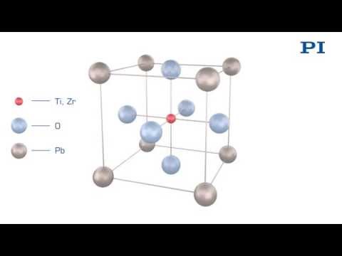
The piezoelectric effect occurs both in monocrystalline materials and in polycrystalline ferroelectric ceramics. In single crystals, an asymmetry in the structure of the unit cells of the crystal lattice, i.e. a polar axis that forms below the Curie temperature TC , is a sufficient prerequisite for the effect to occur.

Piezoelectric ceramics additionally have a spontaneous polarization, i.e. the positive and negative charge concentration of the unit cells are separate from each other. At the same time, the axis of the unit cell extends in the direction of the spontaneous polarization and a spontaneous strain occurs.

The piezoelectric effect of natural monocrystalline materials such as quartz, tourmaline and Rochelle salt is relatively small. Polycrystalline ferroelectric ceramics such as barium titanate (BaTiO3) and lead zirconate titanate (PZT) exhibit larger displacements or induce larger electric voltages. PZT piezo ceramic materials are available in many variations and are most widely used for actuator or sensor applications. Special dopings of the PZT ceramics with, e.g., Ni, Bi, La, Nd, Nb ions make it possible to specifically optimize piezoelectric and dielectric parameters.
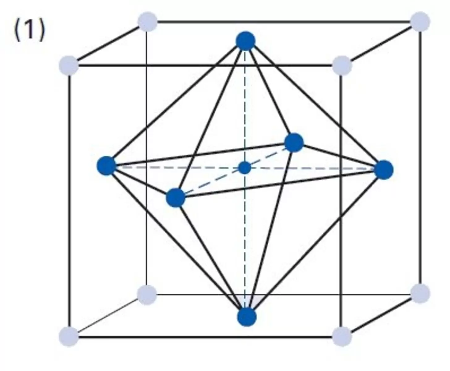
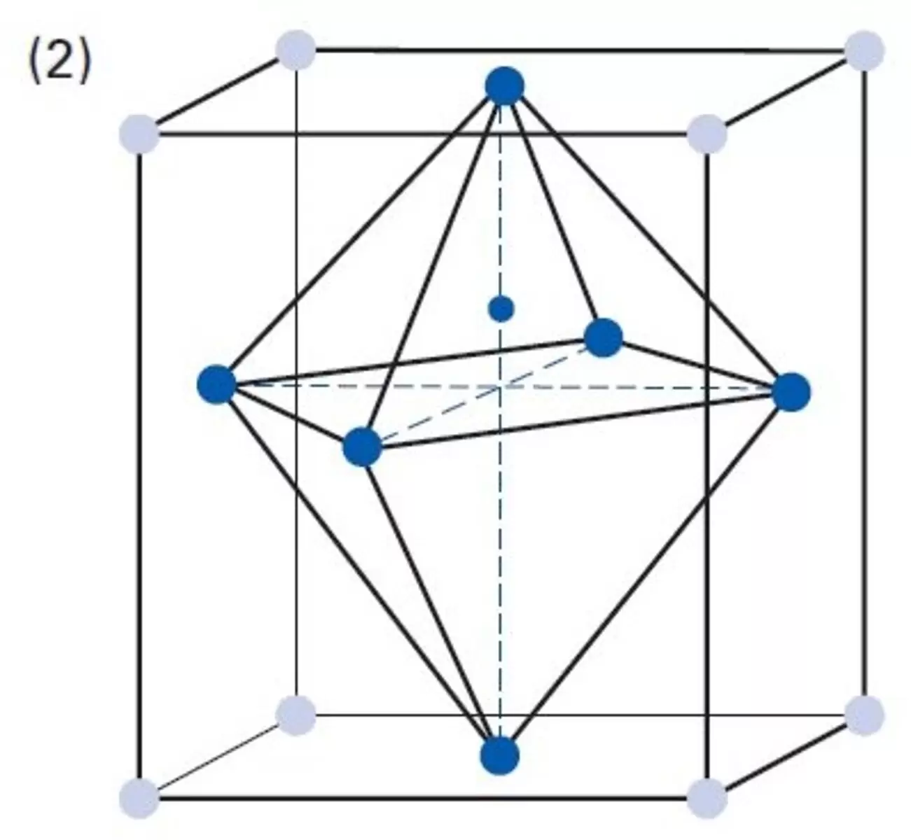
At temperatures below the Curie temperature TC , the lattice structure of the PZT crystallites becomes distorted and asymmetric. This brings about the formation of dipoles and the rhombohedral and tetragonal crystallite phases, which are of interest for piezo technology. The ceramic exhibits spontaneous polarization. Above the Curie temperature the piezoceramic material loses its piezoelectric properties.


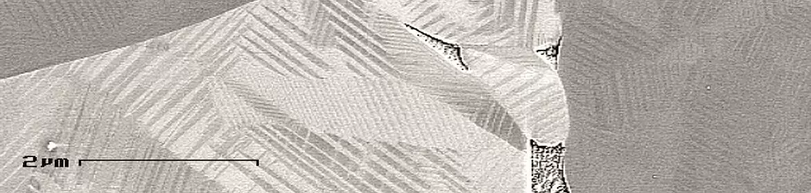
Polarized domains (Image: IKTS Dresden)

Ferroelectric Polarization

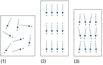
To minimize the internal energy of the material, ferroelectric domains form in the crystallites of the ceramic. Within these volumes, the orientations of the spontaneous polarization are the same.

The different orientations of bordering domains are separated by domain walls. A ferroelectric polarization process is required to make the ceramic macroscopically piezoelectric as well.


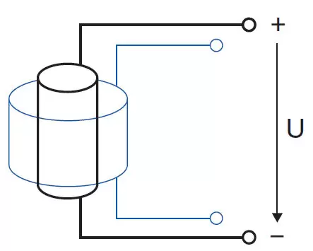
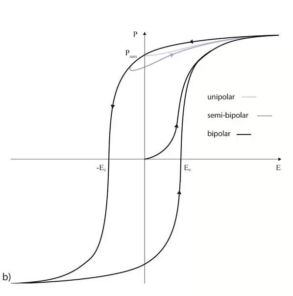
For this purpose, a strong electric field of several kV/mm is applied to create an asymmetry in the previously unorganized ceramic compound. The electric field causes a reorientation of the spontaneous polarization. At the same time, domains with a favorable orientation to the polarity field direction grow and those with an unfavorable orientation shrink. The domain walls are shifted in the crystal lattice.

After polarization, most of the reorientations are preserved even without the application of an electric field. However, a small number of the domain walls are shifted back to their original position, e.g., due to internal mechanical stresses.


Principle of the ferroelectric polarization

Expansion of the Polarized Piezo Ceramic

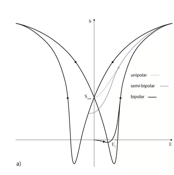
The ceramic expands, whenever an electric field is applied, that is less strong than the original polarization field strength. Part of this effect is due to the piezoelectric shift of the ions in the crystal lattice and is called the intrinsic effect.

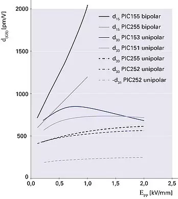
The extrinsic effect is based on a reversible ferroelectric reorientation of the unit cells. It increases with increasing strength of the driving field strength and is responsible for most of the nonlinear hysteresis and drift characteristics of ferroelectric piezo ceramics.


Displacement of ferroelectric piezo
 ceramics at different control amplitudes


Electromechanics

Polarized piezoelectric materials are characterized by several coefficients and relationships.

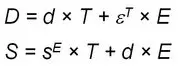
In simplified form, the basic relationships between the electrical and elastic properties can be represented as follows:


D Electric flux density
T Mechanical stress
E Electrical field
S Mechanical strain
d Piezoelectric charge coefficient
εT Permittivity (for T = constant)
sE Compliance or elasticity coefficient (for E = constant)

These relationships apply only to small electrical and mechanical amplitudes, so-called small signal values. In this range, the relationships between mechanical, elastic deformation S or stress T and electrical field E or electrical flux density D are linear, and the values for the coefficients are constant.

These small-signal coefficients can be found in the material data table:

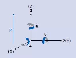
Orthogonal system to describe the properties of a polarized piezo ceramic. Axis 3 is the direction of polarization

Assignment of Axes

The directions are designated by the axes 1, 2, and 3 (corresponding to the axes X, Y, and Z of the Cartesian coordinate system). The rotational axes, known as U, V, W in the coordinate system, are designated with 4, 5, and 6.

The direction of polarization (axis 3) is established during the polarization process by means of a strong electrical field applied between the two electrodes. This is where the largest displacement of the piezoceramic is reached.

Since the piezoelectric material is anisotropic, the corresponding physical quantities are described by tensors. The piezoelectric coefficients are therefore indexed accordingly.


Piezoelectric Coefficients

The permittivity ε or the relative dielectric coefficient DC is the ratio of the absolute permittivity of the ceramic material and the permittivity in vacuum (ε0 = 8.85 × 10⁻¹² F/m), where the absolute permittivity is a measure of the polarizability in the electrical field. The dependency of the dielectric coefficient from the orientation of the electric field and the dielectric displacement is symbolized by the corresponding indices.

Examples:

ε33T DCvalue in the polarization direction when an electric field is applied in the direction of polarization (direction 3) at a constant mechanical stress (T=0: "free" permittivity)

ε11S Electrical field and dielectric displacement in the direction of axis 1, at constant deformation (S=0: "clamped" permittivity)

The piezo modulus is the ratio of induced electric charge to mechanical stress or of achievable mechanical stress to electric field applied (T = constant). For piezo actuators, the piezo modules is also referred to as deformation coefficient.

Example:

d33 Strain produced per unit of applied electrical field in V/m or charge density in C/m2 per unit of pressure in N/m2, each in the polarization direction

The piezoelectric voltage coefficient g is the ratio of the electric field strength E to the effective mechanical stress T. Dividing the respective piezoelectric charge coefficient dij by the corresponding permittivity gives the corresponding gij coefficient.

Example:

g31 Induced electric field in direction 3 per unit mechanical stress acting in direction 1 = force per unit area, not necessarily orthogonal

The elastic compliance coefficient s is the ratio of the relative deformation S to the mechanical stress T. Mechanical and electrical energy are mutually dependent, which is why the electrical boundary conditions such as the electric flux density D and field strength E must be taken into consideration.

Examples:

s33E Ratio of the mechanical strain in direction 3 to the mechanical stress in direction 3, at constant electric field (for E = 0: short circuit)

s55E Ratio of a shear strain to the effective shear stress at constant dielectric displacement (for D = 0: no load).

The frequently used elasticity or Young's modulus Yij corresponds in a first approximation to the reciprocal value of the corresponding elasticity coefficients.

The frequency coefficient N describes the relationship between the geometrical dimension A of a body and the corresponding (series) resonant frequency. The indices designate the corresponding direction of oscillation, A = dimension, N = fS × A.

Examples:

N3 Frequency coefficient for the longitudinal oscillation of a slim rod, polarized in longitudinal direction

N1 Frequency coefficient for the transverse oscillation of a slim rod, polarized in direction 3

N5 Frequency coefficient of the thickness oscillation of a thin plate

NP Frequency coefficient of the planar surface oscillation of a round disk

Nt Frequency coefficient of the thickness oscillation of a thin plate polarized in the thickness direction

The mechanical quality factor Qm characterizes the "sharpness of resonance" of a piezoelectric body or resonator and is primarily determined from the 3 dB bandwidth of the series resonance of the system which is able to oscillate. The reciprocal value of the mechanical quality factor is the mechanical loss factor, the ratio of effective resistance to reactance in the equivalent circuit diagram of a piezoelectric resonator at resonance.

The coupling factor k is a measure of the extent of the piezoelectric effect (not an efficiency factor!). It describes the ability of a piezoelectric material to convert electrical energy into mechanical energy and vice versa. The coupling factor is determined by the square root of the ratio of stored mechanical energy to the total energy absorbed. At resonance, k is a function of the corresponding form of oscillation of the piezoelectric body.

Examples:

k33 Coupling factor for longitudinal oscillation

k31 Coupling factor for transverse oscillation

kP  Coupling factor for radial oscillation (planar) of a round disk

kt   Coupling factor for the thickness oscillation of a plate

k15 Coupling factor for the thickness shear oscillation of a plate

Dynamic Behavior

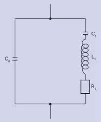
The electromechanical behavior of a piezoelectric body excited to oscillations can be represented by an electrical equivalent circuit diagram.

C0 is the capacitance of the dielectric. The series circuit, consisting of C1, L1, and R1, describes the change in the mechanical properties, such as elastic deformation, effective mass (inertia) and mechanical losses resulting from internal friction. This description of the oscillatory circuit can, however, only be used for frequencies in the vicinity of the mechanical intrinsic resonance.

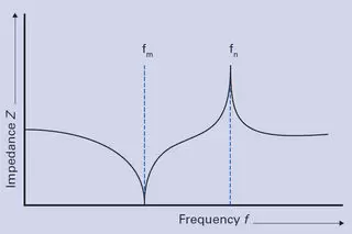
Most piezoelectric material parameters are determined by means of impedance measurements on special test bodies at resonance. The series and parallel resonances are used to determine the piezoelectric parameters. These correspond to a good approximation of the impedance minimum fm and maximum fn.

Equivalent circuit diagram of a piezoelectric resonator
Typical impedance curve

Oscillation States of Piezoceramic Components

Oscillation states or modes and the deformation are decided by the geometry of the body, the mechano-elastic properties and the orientations of the electric field and the polarization.

Direct the future with the power of the past.
Expertise
Markets Technologies
Contact
Nano Dünya Mak. San. Tic. Ltd. Şti.
Parseller Mah. Gündoğan Sok. No:8/A
Ümraniye/İstanbul

02166140039
info@nanodunya.com.tr
Copyright © 2024 by Nano Dünya. All rights reserved.
x
Quote List
Your quote list is currently empty.
x
Download Request
Your download list is currently empty.
0 0 Whatsapp