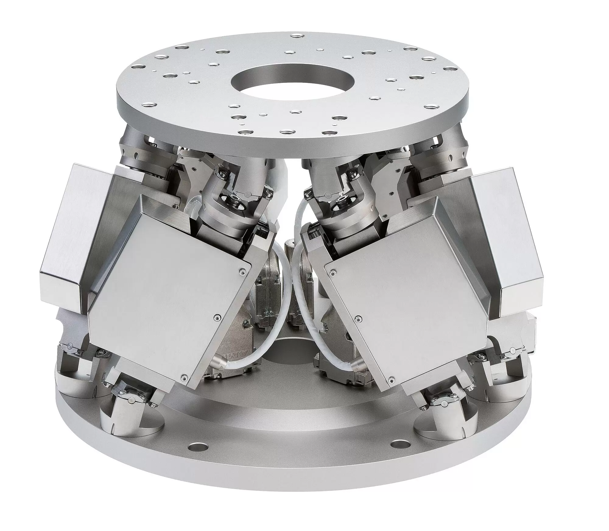
Parallel-kinematic design for six degrees of freedom, making it significantly more compact and stiff than serial-kinematic systems, higher dynamics, no moved cables: Higher reliability, reduced friction. suitable for vacuum environments to 10-6 hPa.
The simulation software simulates the limits of the workspace and load capacity of a hexapod. Therefore, even before purchasing, you can check whether a particular hexapod model can handle the loads, forces, and torques occurring in an application. For this purpose, the simulation tool takes the position and motion of the hexapod as well as the pivot point and several reference coordinate systems into account.
Industry and research. For micromanipulation, biotechnology, semiconductor manufacturing
| Motion | H-824.D2V | H-824.G2V | Tolerance |
|---|---|---|---|
| Active axes | X Y Z θX θY θZ | X Y Z θX θY θZ | |
| Travel range in X | ± 22.5 mm | ± 22.5 mm | |
| Travel range in Y | ± 22.5 mm | ± 22.5 mm | |
| Travel range in Z | ± 12.5 mm | ± 12.5 mm | |
| Rotation range in θX | ± 7.5 ° | ± 7.5 ° | |
| Rotation range in θY | ± 7.5 ° | ± 7.5 ° | |
| Rotation range in θZ | ± 12.5 ° | ± 12.5 ° | |
| Maximum velocity in X | 12.5 mm/s | 0.5 mm/s | |
| Maximum velocity in Y | 12.5 mm/s | 0.5 mm/s | |
| Maximum velocity in Z | 12.5 mm/s | 0.5 mm/s | |
| Maximum angular velocity in θX | 135 mrad/s | 5.5 mrad/s | |
| Maximum angular velocity in θY | 135 mrad/s | 5.5 mrad/s | |
| Maximum angular velocity in θZ | 135 mrad/s | 5.5 mrad/s | |
| Typical velocity in X | 5 mm/s | 0.2 mm/s | |
| Typical velocity in Y | 5 mm/s | 0.2 mm/s | |
| Typical velocity in Z | 5 mm/s | 0.2 mm/s | |
| Typical angular velocity in θX | 28 mrad/s | 2.3 mrad/s | |
| Typical angular velocity in θY | 28 mrad/s | 2.3 mrad/s | |
| Typical angular velocity in θZ | 28 mrad/s | 2.3 mrad/s | |
| Positioning | H-824.D2V | H-824.G2V | Tolerance |
| Unidirectional repeatability in X | ± 0.5 µm | ± 0.4 µm | typ. |
| Unidirectional repeatability in Y | ± 0.5 µm | ± 0.4 µm | typ. |
| Unidirectional repeatability in Z | ± 0.15 µm | ± 0.1 µm | typ. |
| Unidirectional repeatability in θX | ± 3 µrad | ± 2 µrad | typ. |
| Unidirectional repeatability in θY | ± 3 µrad | ± 2 µrad | typ. |
| Unidirectional repeatability in θZ | ± 2.5 µrad | ± 3 µrad | typ. |
| Minimum incremental motion in X | 2 µm | 0.3 µm | typ. |
| Minimum incremental motion in Y | 2 µm | 0.3 µm | typ. |
| Minimum incremental motion in Z | 1 µm | 0.3 µm | typ. |
| Minimum incremental motion in θX | 12 µrad | 3.5 µrad | typ. |
| Minimum incremental motion in θY | 12 µrad | 3.5 µrad | typ. |
| Minimum incremental motion in θZ | 14 µrad | 3.5 µrad | typ. |
| Backlash in X | 3 µm | 5 µm | typ. |
| Backlash in Y | 3 µm | 5 µm | typ. |
| Backlash in Z | 1.5 µm | 1.5 µm | typ. |
| Backlash in θX | 20 µrad | 30 µrad | typ. |
| Backlash in θY | 20 µrad | 30 µrad | typ. |
| Backlash in θZ | 60 µrad | 45 µrad | typ. |
| Drive Properties | H-824.D2V | H-824.G2V | Tolerance |
| Drive type | DC motor | DC gear motor | |
| Nominal voltage | 24 V | 24 V | |
| Mechanical Properties | H-824.D2V | H-824.G2V | Tolerance |
| Stiffness in X | 1.7 N/µm | 1.7 N/µm | |
| Stiffness in Y | 1.7 N/µm | 1.7 N/µm | |
| Stiffness in Z | 7 N/µm | 7 N/µm | |
| Maximum holding force, base plate in any orientation | 5 N | 25 N | |
| Maximum holding force, base plate horizontal | 15 N | 50 N | |
| Maximum load capacity, base plate in any orientation | 1.25 kg | 2.5 kg | |
| Maximum load capacity, base plate horizontal | 2.5 kg | 5 kg | |
| Overall mass | 8 kg | 8 kg | |
| Material | Aluminum | Aluminum | |
| Miscellaneous | H-824.D2V | H-824.G2V | Tolerance |
| Connector for supply voltage | LEMO | LEMO | |
| Vacuum class | 10⁻⁶ hPa | 10⁻⁶ hPa | |
| Recommended controllers / drivers | C-887.5x | C-887.5x | |
| Cable length | 2 m | 2 m | |
| Operating temperature range | -10 to 50 °C | -10 to 50 °C | |
| Maximum bake out temperature | 80 °C | 80 °C | |
| Connector for data transmission | HD D-sub 78-pin (m) | HD D-sub 78-pin (m) |
Technical data specified at 22±3 °C.
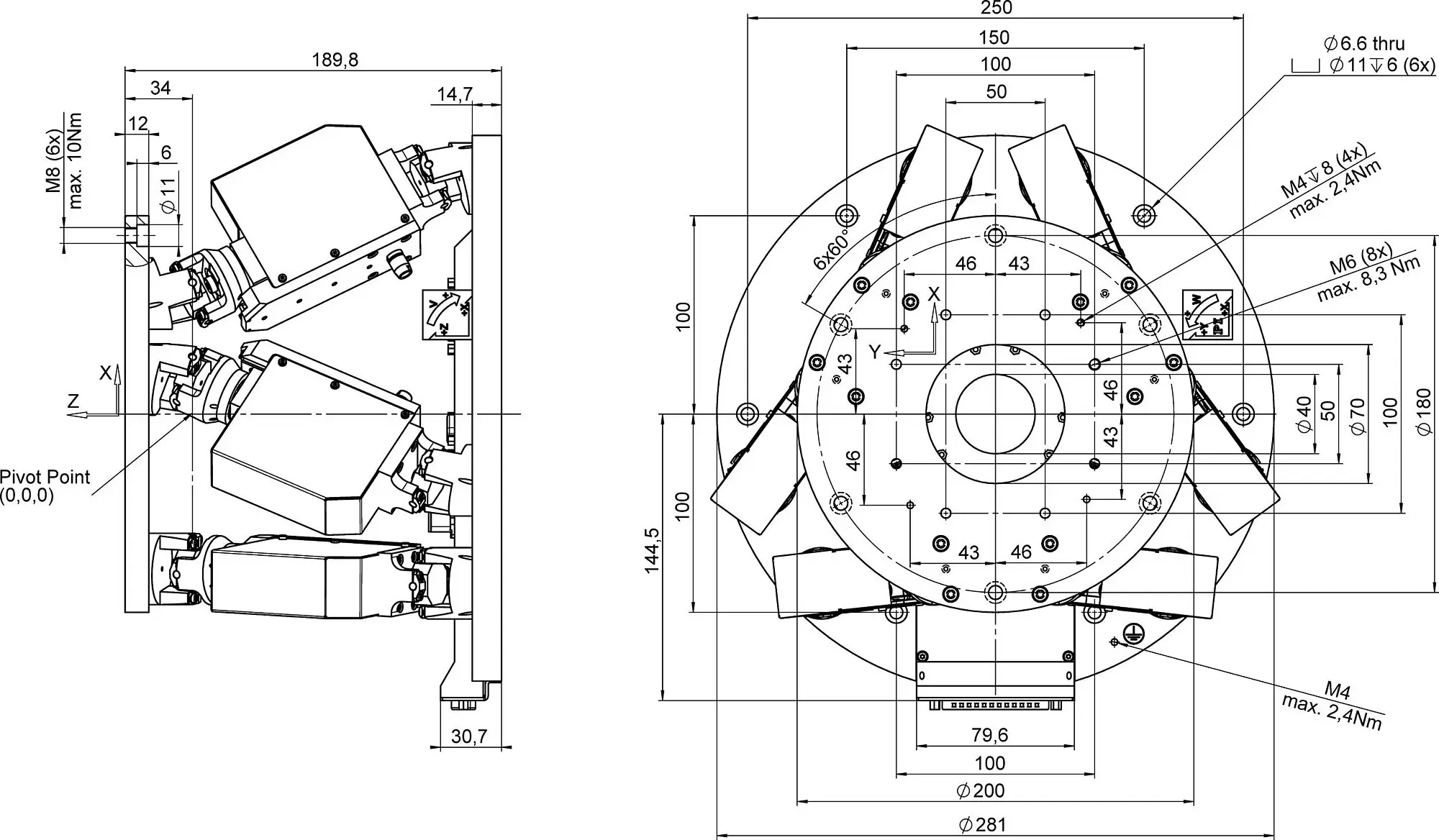
The maximum travel ranges of the individual coordinates (X, Y, Z, θX, θY, θZ) are interdependent. The data for each axis shows its maximum travel range when all other axes are in the zero position of the nominal travel range and the default coordinate system is in use, or rather when the pivot point is set to 0,0,0.
For continuous operation in a vacuum, restrictions on operating parameters may be necessary due to heat generation.
Air-side connecting cables are not included in the scope of delivery and must be ordered separately.
Ask about customized versions.